TURBOGAZ INNOVATIVE SOLUTIONS
THE FUTURE STARTS WITH INNOVATION
DELIVERING LOCALIZED, ENERGY-EFFICIENT TECHNICAL SOLUTIONS
ABOUT

TURBOGAZ INNOVATIVE SOLUTIONS specializes in localizing innovative technical solutions and energy-efficient products for the industrial sector of the Republic of Uzbekistan.

We focus on:

  • equipment modernization and efficiency improvement;
  • comprehensive turnkey engineering solutions.

Our partners

PrJSC “TURBOGAZ” (Ukraine)
TURBOGAZ POLAND (Poland)

Thanks to close cooperation with international partners, we offer:

  • localization of industrial equipment turnaround services;
  • implementation of innovative technical solutions tailored to the specific local market requirements.


We are committed to promoting sustainable development and enhancing the energy efficiency of Uzbekistan’s enterprises, creating new opportunities for the country’s industrial growth.

The company is registered in accordance with the law of the Republic of Uzbekistan on the ground of the Law On State Registration of Legal Entities and Individual Entrepreneurs, No. ZRU-370 dated December 05, 2014.

OUR PARTNERS

Role: Engineering center and production facilities

Structure and activities:

  • North-Eastern Production Site. Specializes in the repair of changeable flow channels (plug-in units) and serves customers in Central and Eastern Ukraine.
  • The Transcarpathian Production Site focuses on the manufacture of expander-compressor and expander-generator equipment and supplies products to international customers.

Role: Financial operator and logistics provider

Functions:

  • Supports international financial transactions.
  • Ensures the supply of EU-based components.
  • Organizes storage, transportation, and comprehensive logistical support.
OUR SERVICES
LOCALIZATION OF TURNAROUND SERVICES
  • Maintain equipment in safe operating condition, ensuring high performance and reliable, uninterrupted operation;

  • Minimize equipment downtime and reduce costs associated with all types of repairs;

  • Ensure prompt response and rapid support in the event of unplanned equipment outages;

  • Guarantee the availability of spare parts and repair kits for timely, high-quality maintenance;

  • Provide 24/7 technical support (online and on-site).

LOCALIZATION OF PRODUCTION

Localization of rotary spare parts manufacturing. Up-to-date production capabilities and reduced logistics costs significantly shorten equipment lead times and improve availability

SERVICING

Our service support includes:

  • supervision of installation and commissioning of supplied equipment;
  • technical evaluation and modernization of the Customer’s process equipment;
  • diagnostics and repair of equipment for the oil, gas, and energy industries.
ENGINEERING
  • equipment selection and design;
  • gas-dynamic and thermal calculations;
  • modeling of gas treatment process flow diagrams;
  • modernization and optimization of existing equipment;
  • development of design documentation in compliance with international standards (API, ASME, ISO).
EQUIPMENT
Expander Compressor
Expander Generator
Multi-Stage Centrifugal Gas Compressor
Compander
Lube Oil System
Gas Treatment Units
Dry Gas Seals
EXPANDER COMPRESSOR

An expander compressor is designed for deep cold generation in gas treatment and processing units by temperature drop up to 55°С.

By outlet pressure the following expander compressors may be used:

  • For natural gas refrigeration (minus 2°С)
  • For C+ recovery (up to minus 30°С)
  • For LPG production (up to minus 80°С)
  • For low-temperature gas separation at olefin production (up to minus 153°С)


Expander compressors are used for:

  • For low-temperature gas treatment and refrigeration for further transportation.
  • For gas processing at gas refineries by natural gas low-temperature heavy-end fractionation.
  • For various technical gases (O, N, Ar, etc.) production in air separation units by low-temperature air separation.


Specifications:

  • Inlet pressure: max. 209 bar
  • Temperature: from –200°C to +280°C
  • Bearing type: AMB or OB
  • API 617 compliance: Yes


Note:

AMB – active magnetic bearing

OB – oil bearing

EXPANDER GENERATOR

Expander Generator is designed for:
• Power generation at natural gas reduction points of gas distribution stations, gas distribution points of large gas consumers – CHP plants, metallurgical, chemical plants and other large consumers of gas transmission systems.
• Power generation during reduction of various process gases with excessive pressure: in chemical, petrochemical, metallurgical and other industries.

• Generation of electricity by regasification of liquefied natural gas.

• Generation of electricity by utilization of low-potential (low-pressure) heat (ORC-cycle or Rankine cycle).
• Generation of electricity for gas reduction points’ in-house needs.

Specifications:

– Capacity: min. 8 kW, max. 16 MW.
– Pressure range: max. 6.3 MPa
– Gas consumption: 0.05 – 20.0 mln. Nm3/day
– Various designs of expander-generators:
• Rolling Bearing-based
• Slide (Journal) Bearing-based
• Active Magnetic Bearing-based

MULTI-STAGE CENTRIFUGAL GAS COMPRESSOR

The compressors are used to compress almost all types of gases:


hydrocarbons (HC)
nitrogen (N2)
natural gas (NG) including those with a high content of hydrogen sulfide (H2S).
In this case, materials for the design of the compressor flow passage are selected in accordance with NACE MR 0175 / ISO 15156-1: 2001 (E).

Centrifugal compressors are designed for the following process parameters:
Capacity corresponds to inlet conditions: 500 to 150 000 m3/h
Discharge pressure up to 200 bar
Discharge temperature up to +200 °С
Compressor inlet temperature varies over a wide range from -195 °С to + 100 °С
Designed as per API 617.


The following drives are used:
– Synchronous or induction electric motors (equipped with a frequency controller (VFD)

-Steam turbines made in compliance with API 611 & 612

COMPANDER

It combines functions of a compressor and a turbine in a single unit. It enables the use of a more powerful compressor than a turbine by using an electric motor or other source of mechanical energy. This solution is designed to improve energy efficiency and reduce capital costs in various industrial processes, especially in the oil and gas, chemical and energy industries.

Specifications:

LP compressor
Flow, kg/h: 93 935
Inlet pressure, MPa (abs.): 0.1
Outlet pressure, MPa (abs.): 0.3
Inlet temperature, °C: 10.0
Outlet temperature, °C: 134.3
Number of stages: 3
Capacity, kW: 3315

HP compressor
Flow, kg/h: 93 935
Inlet pressure, MPa (abs.): 0.29
Outlet pressure, MPa (abs.): 0.92
Inlet temperature, °C: 51.3
Outlet temperature, °C: 199.8
Number of stages: 3
Capacity, kW: 4017

Turbine
Flow, kg/h: 81 910
Inlet pressure, MPa (abs.): 0.88
Outlet pressure, MPa (abs.): 0.113
Inlet temperature, °C: 179.8
Outlet temperature, °C: 20.0
Number of stages: 3
Capacity, kW: 3792

Electric motor

Capacity, kW: 3690

LUBE OIL SYSTEM

Lube oil systems are designed and manufactured in accordance with API 614 “Lubrication and Sealing Systems for Auxiliary Equipment in the Oil, Gas and Chemical Industries” or any other customer requirements.


Purpose: lube oil system is designed to lubricate and cool bearing assemblies and shaft seals of the following equipment:
– expander compressors;
– compressors;
– expander generators;
– pumps;
– electric motors;
– turbogenerators;
– gearboxes.


Lube oil system components:
– skid;
– oil tank with built-in electric oil heater and level indicator;
– oil separator (drip pan);
– pump units (main and backup);
– dual fine filter with switching device;
– oil pump suction side coarse filters;
– piping with control, shut-off and safety valves;
– oil cooler;
– oil accumulators or reserve oil tank;
– control and measuring instruments and electrical equipment.

Designs:
– closed (with excess pressure at oil tank);
– open (with atmospheric pressure)
– Built-in oil system

GAS TREATMENT UNITS

Gas Treatment Units are intended for complex gas media preparation to be used in gas pumping units and gas pumps of compressor stations. The treated gas is further used as pulse and buffer gas for dry gas-dynamic seals of compressors.


The following processes are provided by Gas Treatment Units:
• gas cleaning from mechanical impurities and undesirable components;
• reduction to the required pressure parameters;
•treatment and purging of gas before delivery to the consumer;
• automatic introduction of odourants, special additives contributing to a gas characteristic odour for timely detection of leaks.


The equipment includes:
• gas cleaning units;
• fuel gas reduction unit;
• gas metering unit;
• automatic gas odorization unit.

The comprehensive use of such modules ensures reliable, safe and efficient operation of gas transmission systems.

DRY GAS SEALS

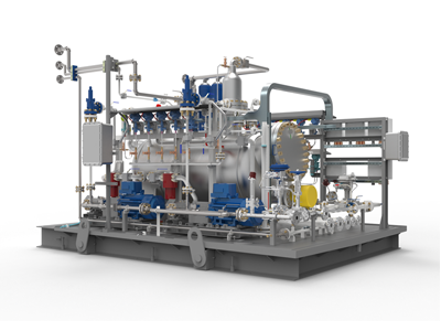
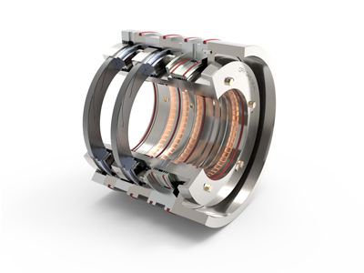
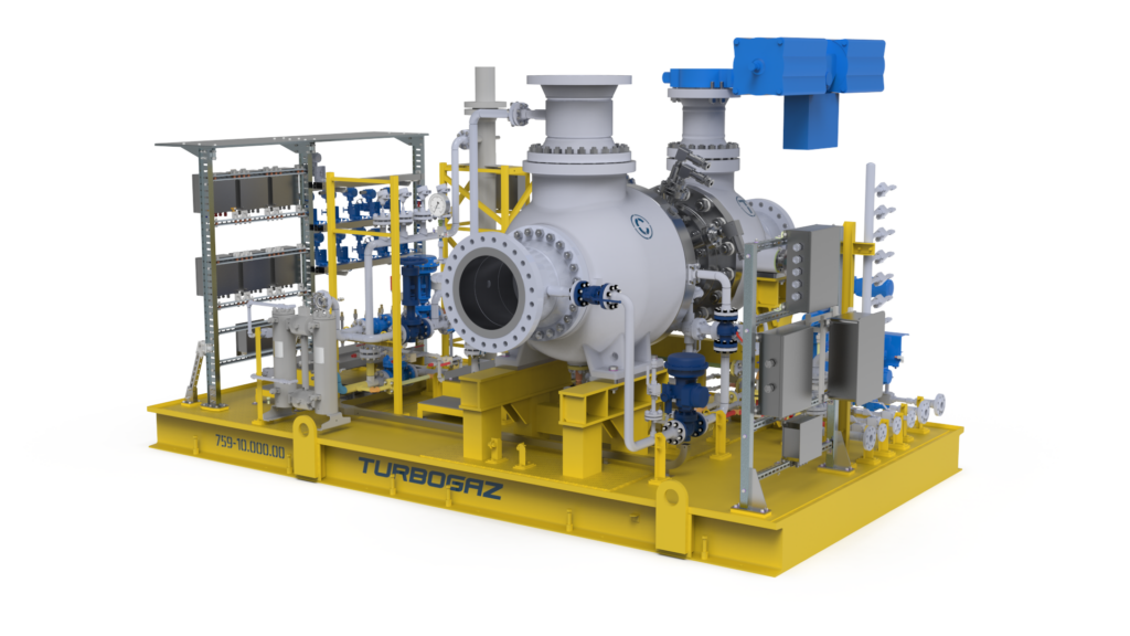
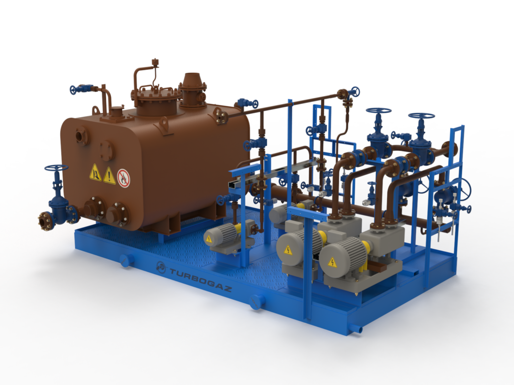
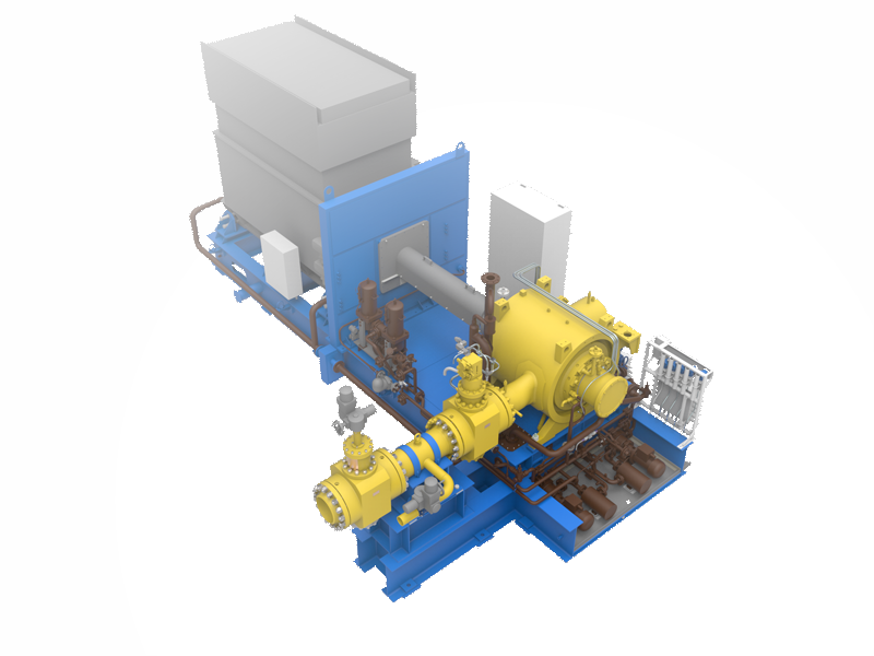
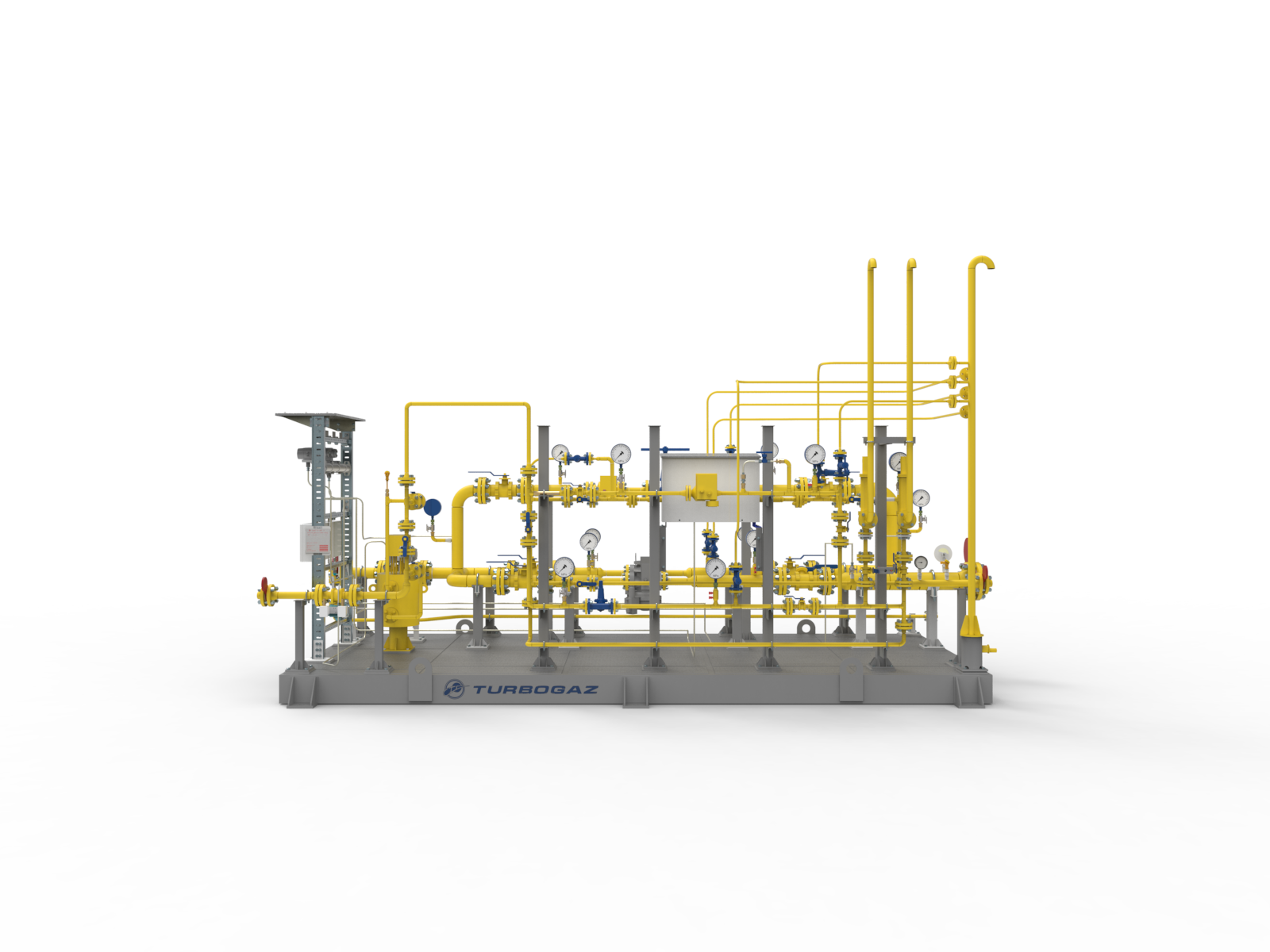
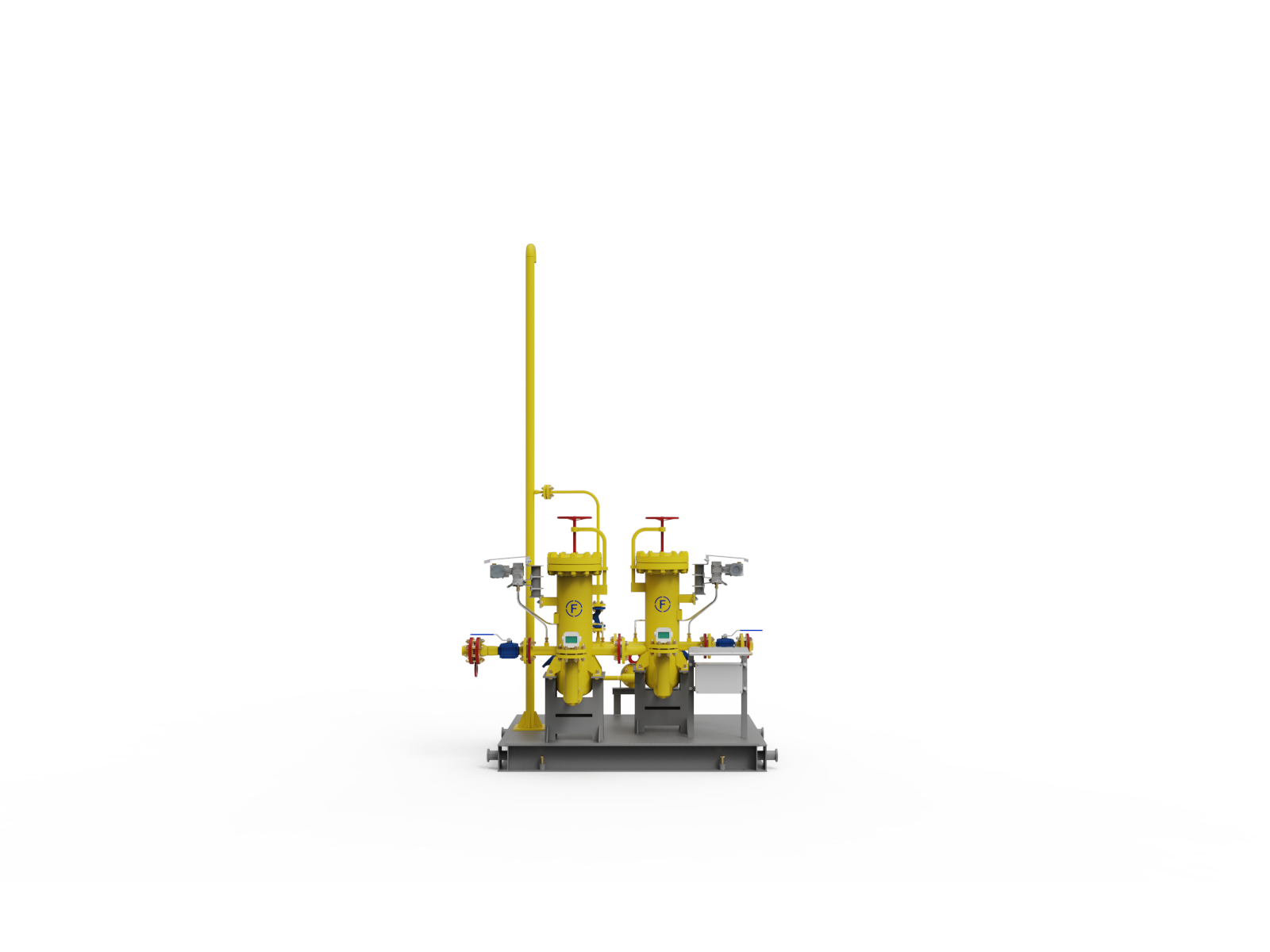
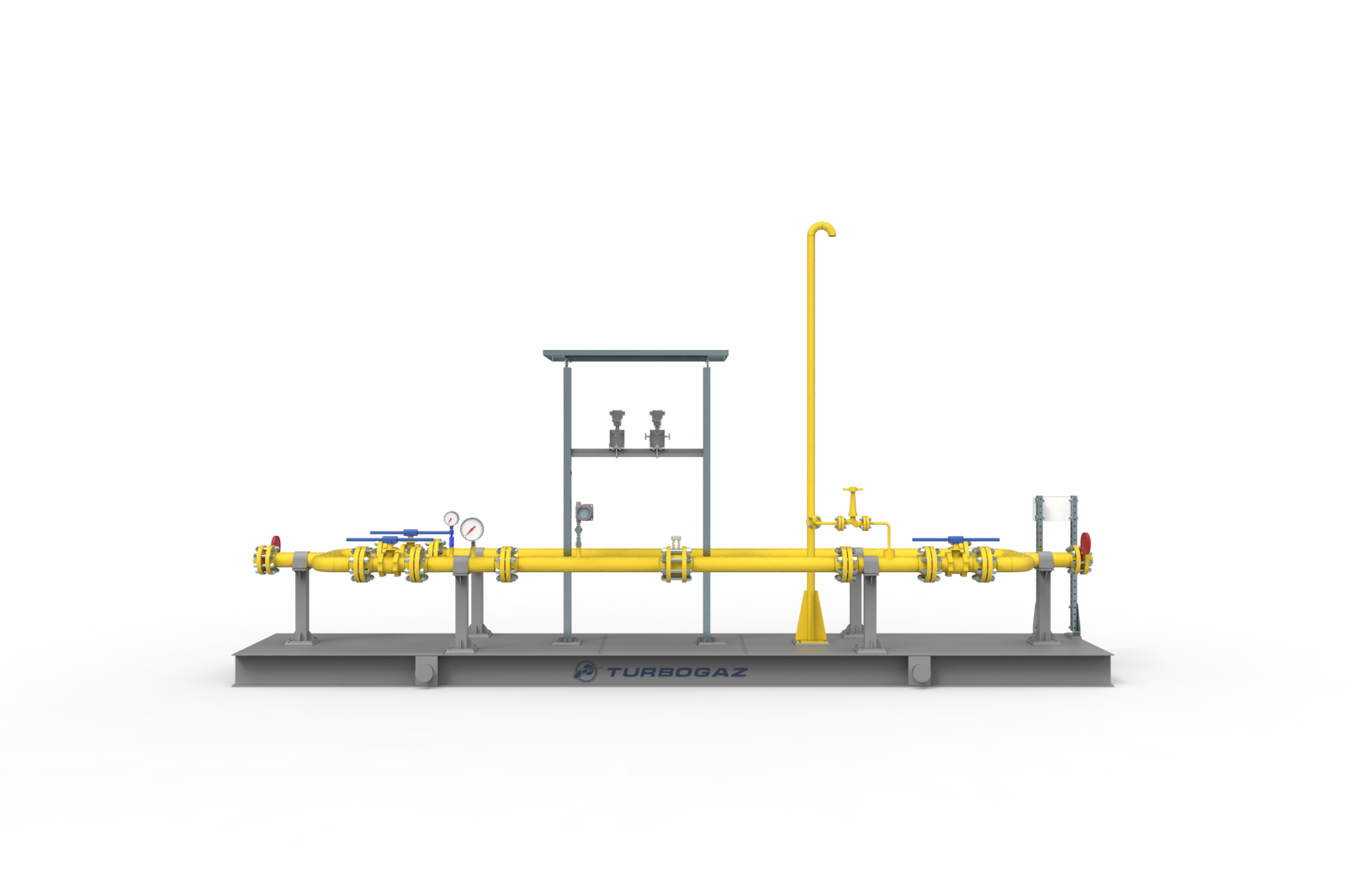
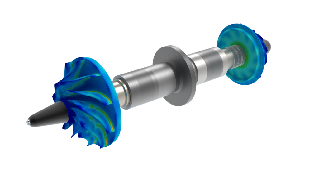
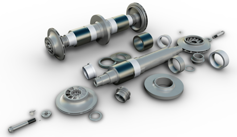
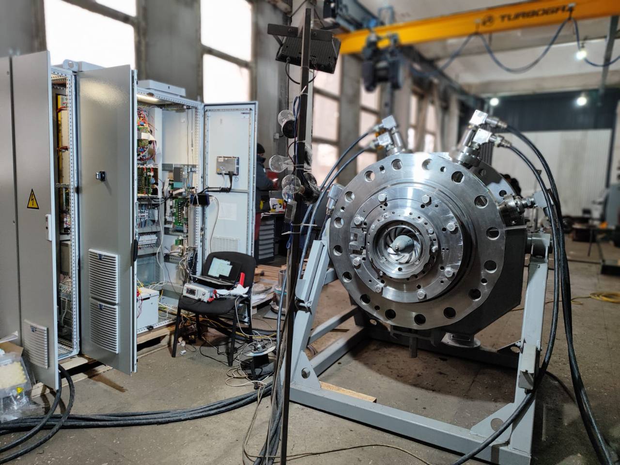
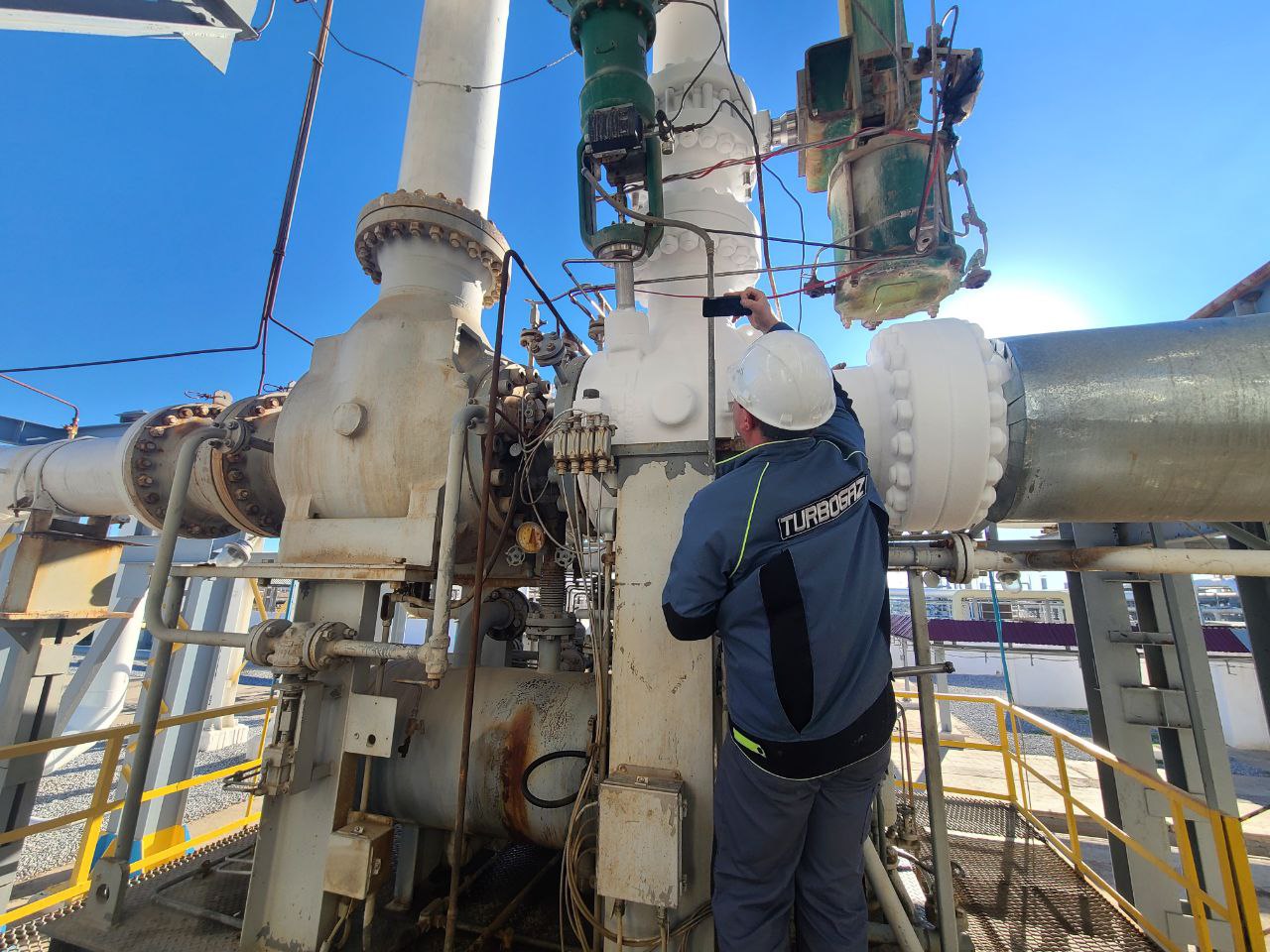
Dry gas seal systems (DGS) are the most effective solution for turbomachinery shaft sealing.

Dry gas seal systems are the most advanced seals for turbomachinery shafts. Dry gas seal systems can be used on virtually any equipment where there is a need to seal rotating shafts.

Specifications:

Sealing pressure – max. 250 kg/cm2;
Seal area temperature – max. 250 ºС;
Peripheral speed of rotating seat – max. 160 m/sec;
Sealed shaft diameter – max. 300 mm.

If any of the specified parameters are exceeded, special (customized) seals can be used.

DGS are used due to a number of economic and environmental advantages in comparison with traditional shaft end seal systems:

• elimination of oil losses ablating to the flow range;
• elimination of losses associated with unusable oil replacement;
• reduction of working gas losses by ten folds due to oil discharge cut-off from oil traps and degassers;
• operating gas quality improvement by eliminating the oil content;
• no energy costs for the operation of seal oil pumps;
• no energy costs for oil degassing;
• reduction of sealing system maintenance time losses;
• reduction of standard and above-standard emission fees;
• reduction of losses from excess energy and gas consumption during unscheduled shutdowns due to seal failures;
• improvement of environmental friendliness;
• improvement of operating conditions;
• improvement of fire and explosion safety.

Maintenance benefits:
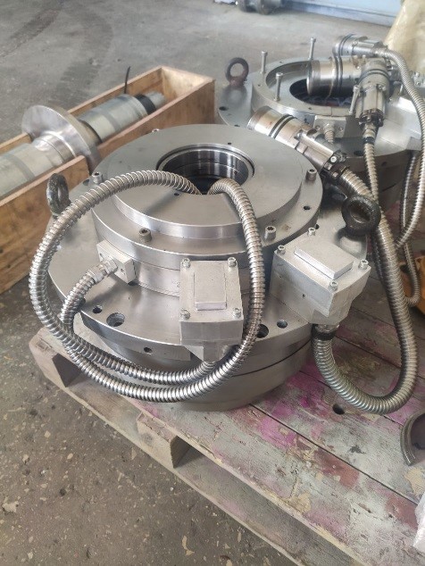
no labor-intensive process of sealing oil system maintenance (oil replacement, repair of pumps and related equipment, the entire system inspection);

dry gas seal maintenance includes: visual inspection of operating sealing steam, replacement of O-rings and dampers (once per 1…4 years), replacement of clogged filter elements, standard periodic calibration of instruments.

Limited Liability Company

“TURBOGAZ INNOVATIVE SOLUTIONS”.

Barhayot MFY, 12 mavzesi , 20а-uy, Yunusabad district,

city of Tashkent, the Republic of Uzbekistan.

Тел. +998 50 703 2357
turbogaz.uz@gmail.com
www.turbogazis.uz

© 2025 – 2026 TURBOGAZ INNOVATIVE SOLUTIONS